Inception
I wanted to explore the realms of physical/digital worlds and recognize how much potential is unlocked by bridging the two. Technologies such as RaspberryPi and Arduino have made this type of project relatively accessible, offering extensive interactivity between software and electronics. I had an Artin (Scalextric) slot car set from my childhood gathering dust in my loft so I decided to modernise it by creating a system to control the cars via the accelerometer in a mobile device.
Tech
I opted to use a RaspberryPi which would run a socket server to interface with a custom-built electronic circuit controlling the cars. The main benefits of using the Pi were two-fold. As the Pi is based on Linux OS, code can be written in high level languages without having to learn a language specific to the device such as the Arduino event loop. It also has more networking capabilities out of the box, the RaspberryPi 3 Model B having built in Wi-Fi.
Despite Python being the most popular language for RaspberryPi, I chose to write the server code using GoLang, partly as a learning exercise but also because of its cross-compilation capabilities. A binary can be compiled for the ARM chipset on a development machine and then run directly on the Pi, negating the need for any interpreters to be installed.
Process
As this was my first experience coding for electronics, I started off with a simple exercise, turning on some LEDs via the Pi. After achieving this I moved onto varying the brightness of the LEDs. This is achieved by toggling the pin on and off at a certain frequency above human perception, known as PWM (Pulse Width Modulation). Initially I wrote software in Go to achieve this but found this wasn’t particularly performant due to the OS interrupting the CPU. After some research I found a hardware PWM interface, pi-blaster which exposes a FIFO (First In First Out) file which applications can write to, e.g. echo "17=1" > /dev/pi-blaster which turns pin 17 to full brightness. I also found a library which wrapped this interface in Go go-pi-blaster.


The next step was to write the server code so the LED brightness could be controlled over the network. The socket server is written on top of the Gorilla websocket package. The code enables messages streamed in the format <pin name>=<value> to control the brightness of an LED e.g. streaming the message 1=0.5 will set pin 1 to half brightness. Pin names are configured by passing arguments to the binary when starting the application e.g. 1=17, 2=27. Pins will be released when a client sends the CloseNormalClosure (1000 code), so the next device to connect will control the first available pin.
Now I needed a user interface to send accelerometer data to the socket server. I wrote the frontend application as a Webapp primarily because they are device agnostic and don’t require any app installation. I used the Angular webapp framework which is arguably overkill for this use-case but I like its observable focus, fast build times and test-driven approach using the CLI. To extract accelerometer data I used the Device Orientation Web API. Initially I allowed the user to select which axis to use for control to give me insight into which was more natural for car control. Later I fixed this to to the Y (beta) axis which mimicked the action of an accelerator pedal as the device is tilted forward. The socket client is written using the WebSocket API and will disconnect from the server when the page is unloaded or when the window loses focus (blur event) and connect on page load or a focus event.
So now that I had a device controlling the brightness of the LEDs, it was time to control the slot cars! I prototyped a circuit which varied the track voltage using transistors fed by the Pi’s GPIO PWM output. One of the issues I encountered was that the cars would randomly speed up and down at intervals. This was caused by the power supply not producing an adequately smoothed voltage. A fairly large capacitor was required to smooth out the AC component. I also had an issue with transistors overheating over extended time periods. This was solved by increasing the current rating of the components and providing a heat sink so they could dissipate heat more effectively.
This is a diagram of the circuit, note the diode protecting the transistors from back EMFs (electromagnetic fields) that are produced by the motor.


This is the final circuit. The track slots in via the black box, positive is the brown wire and negative the yellow wires. The track power supply is connected via the black wires in the centre. The black rectangle on the circuit board is a heat-sink housing the transistors which are controlled by the RaspberryPi GPIO pins connected on the right-hand side. Green is track 1, yellow is track 2 and black is the Pi ground.

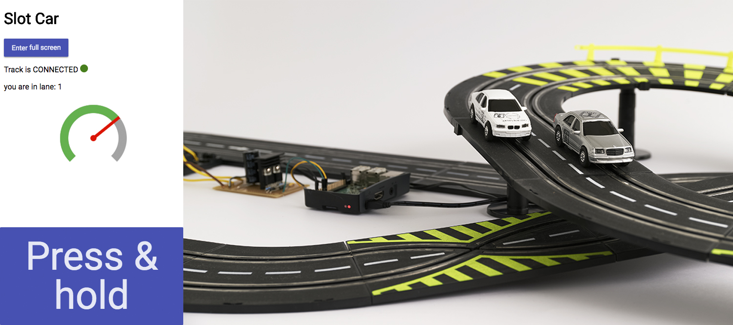
Demo
Here is the finished system in action. The screen in the top corner is controlling the inside lane and the screen in the bottom corner is controlling the outside lane. The user holds down the ‘Press and go’ button which triggers accelerometer data to be streamed to the cars. This is indicated by the tachometer bar changing from red to green.
End Result
I found that controlling the cars using the accelerometer in an accelerator-pedal motion to be a natural and effective experience. By bringing this rather one-dimensional game into the digital domain it has expanded its potential with the possibility of future features like lap timing and counting, race control and power-ups which will ultimately create a more engaging game.